Building Wrenton - Page 6
May-June 2015
The Church
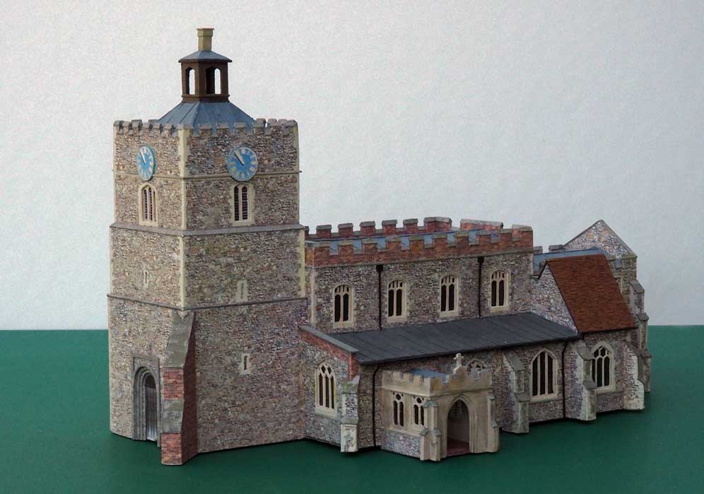
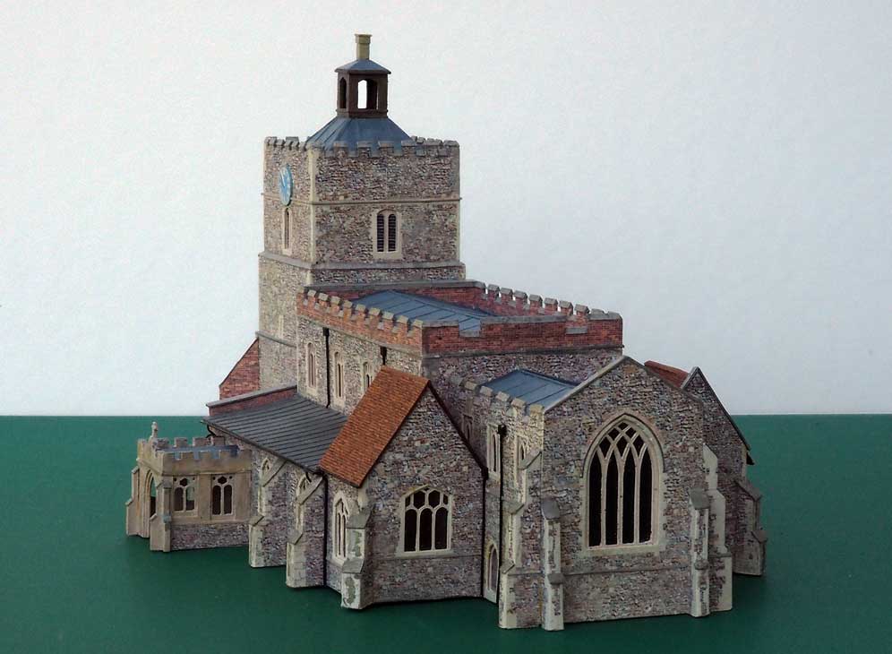
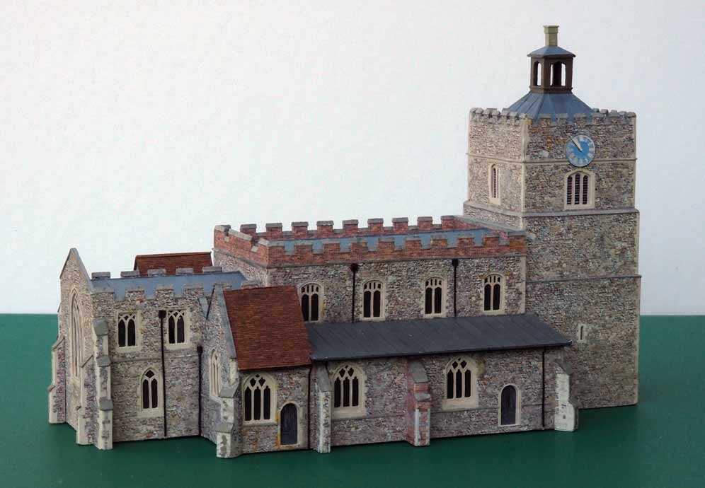
At about eight inches long, this is the largest and most complex building for the layout (I hope!). Like many East Anglian churches the prototype is quite large for the size of the village it serves. I had to reduce the size overall by about 10% and shorten the nave (four windows instead of five) and the chancel (three instead of four) but hopefully something of the character of the original has been retained. It took about seven weeks to make the model, but I'd already spent ages making and modifying drawings and assembling paper mock-ups.
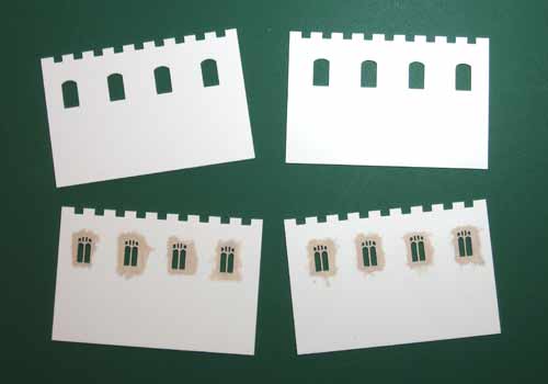
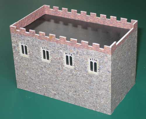
Construction is my usual plastikard. The walls are two layers of 20 thou, the outer one having cutouts for the windows and the inner one having the framing of the windows. There are ten different shapes of window. They were cut with the Silhouette cutter.
The photo shows the parts for the side walls of the nave with the frame layer painted with stone colour.
The printed stone texture was developed from a photo of the actual church and the matching of the printed window surrounds and cutouts in the plastikard was achieved in the same way as for the station building already described.
After the photo was taken small pieces of triangular section Plastruct were fitted to the castellations and painted.
The glazed windows (except for those in the porch) are backed with dark paper and each section of the building is lined with quarter inch thick balsa.
I did once go up the tower of the real building and took some photos of the surrounding views. I just wish I'd taken some which showed the roof! So that area is pure guesswork.
July 2015
Tunnel Portal
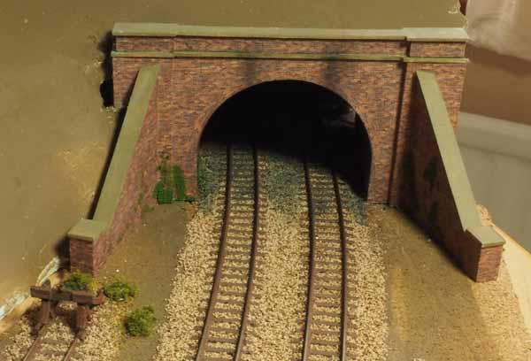
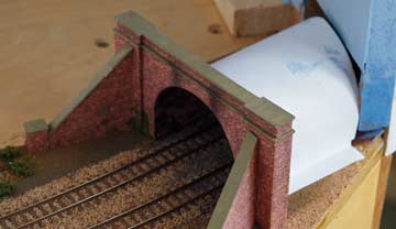
The portal is made from Plastikard and covered with home printed brick paper. I used the Silhouette cutter to make the curve of the tunnel mouth.
The short tunnel lining was made by wrapping and glueing several layers of paper around a suitably sized jar. When the glue was dry I cut the resulting cylinder and lined it with brick paper.
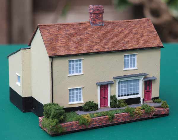
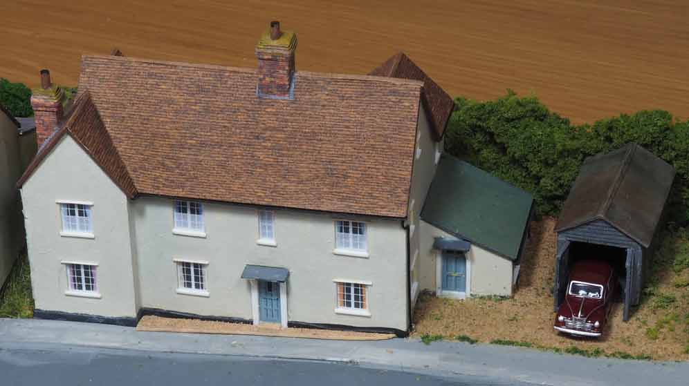
Nos.7 to 9 Church Hill
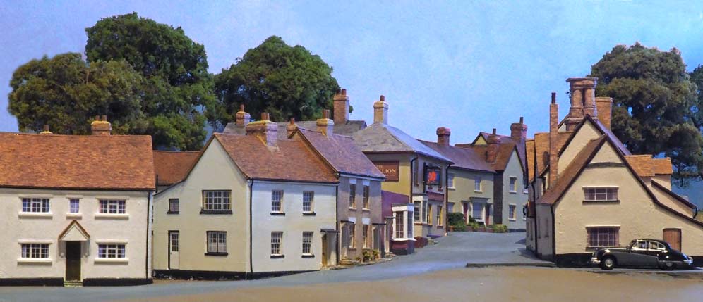
Before starting to assemble the first section of the village I needed a couple more buildings which go beyond the Red Lion.
I forgot to photograph the second one before installing it, so the picture, below, shows it in place, right at the back of the baseboard.
July-August 2015
A Base For Some Scenery
The scenic section of the baseboard is 75cm wide and I didn't think I would be able to detail areas to the rear of the layout leaning across that width. Would it be possible to build the scenery as a free-standing unit which could be fixed onto the baseboard only when it was nearly complete? I decided to try making the right hand end of the area behind the trackwork to see if I could make it work.
Here again is the diagram showing an approximation of the proposed layout of the buildings on the right hand side of the layout. The baseboard joint runs through Nos.2 and 3 The Causeway and that building will have to straddle the joint and be removable.
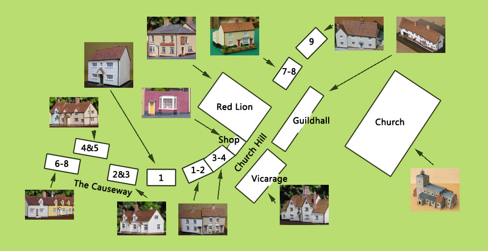
The area to be built includes a hill along which several of the buildings, already made, had to be sited. The gradient of the hill was therefore dictated by that implied by the buildings. The usual methods of making the shell of the scenery didn't look likely to work. And, hard as I looked, I couldn't find any tips for making a ground structure which included a slope which had to be so precisely defined.
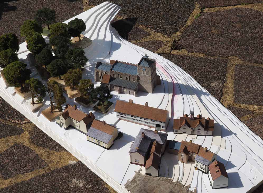
I decided to build up the structure layer by layer, using 5mm thick foamboard. I started by cutting a piece of paper the size of the area to be constructed - the full length of the section of baseboard, 95cm, and about 65cm wide. I positioned the buildings on the paper and drew lines around them. I then measured the required change in ground level each building required and was thus able to work out the changes in ground level all the way up the hill. The foamboard being 5mm thick I then worked out where each layer had to be cut, extending lines out from the road into the adjoining areas to form a countour map. The church was to be included in this group of buildings, so a fairly flat area was needed for that and I also had to work out the shaping of the cutting through which the track will run.
I then cut foamboard to the required shapes and glued the layers together. To eliminate any risk of the structure flexing I cut slots in the third and fourth layers from the bottom into which I inserted a couple of 10mm diameter steel rods. To make the road area levels more precise I added pieces of mounting board. All the buildings have 'foundations' so cutouts were made for them to 'plug' into.
I put the buildings temporarily in place, together with some trees to give an idea of how the whole scene will be arranged. Not all the mounting board pieces are in place yet, and some levels were lowered a layer after seeing this trial assembly.
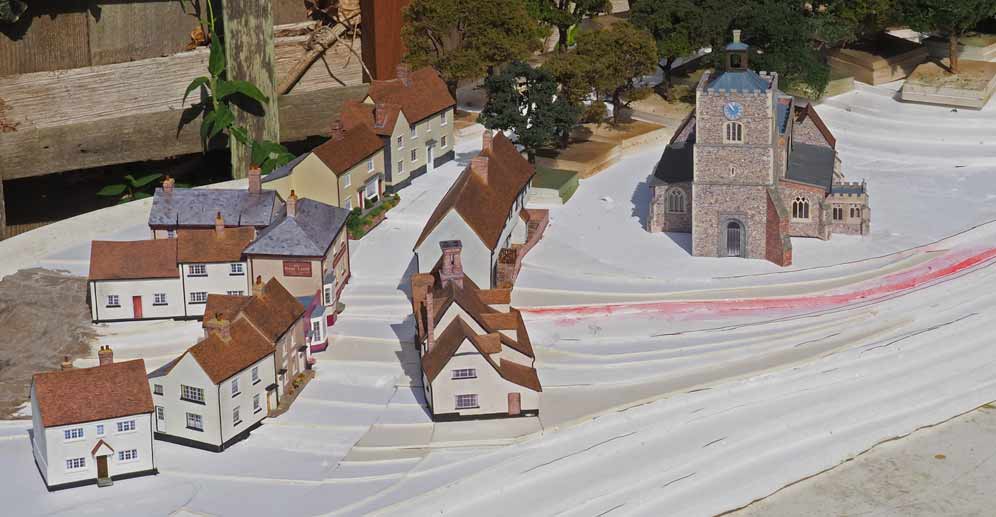
Here's a view from a passing plane. The bit that sticks out at the far end goes over the tunnel mouth.
When I was happy with the levels I coated the whole thing with plaster. Then came a layer of plaster bandage, though not in the road area which obviously had to be kept very smooth. When that had dried it was time to spray paint the whole thing. First, though, Inspector Tilly came to check the work.
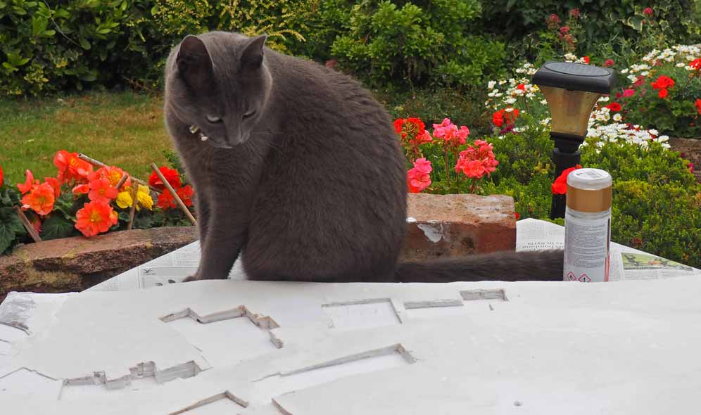
After several attempts to tempt Tilly to move out of the danger zone I sprayed the base with Humbrol acrylic dark brown and the road with grey (which looks rather blue in the photo).
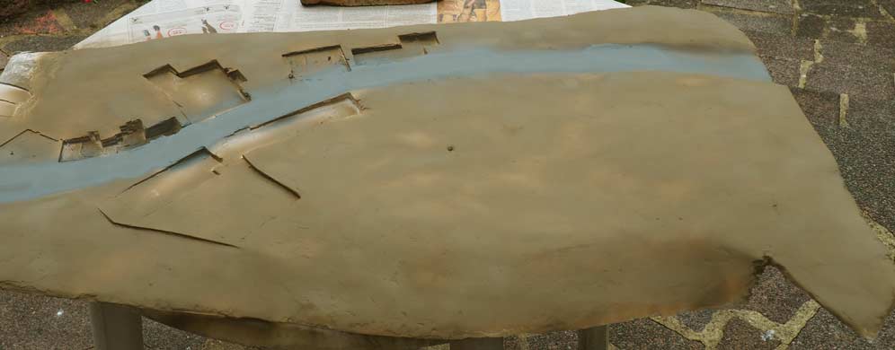
The buildings, except for the church, were installed next and the whole structure was checked in place on the baseboard. A few trees were added for this photo which finally allows me to see if I've got the scene I was hoping to create.
