Building Wrenton - Page 5
October-November 2014
The Station Building
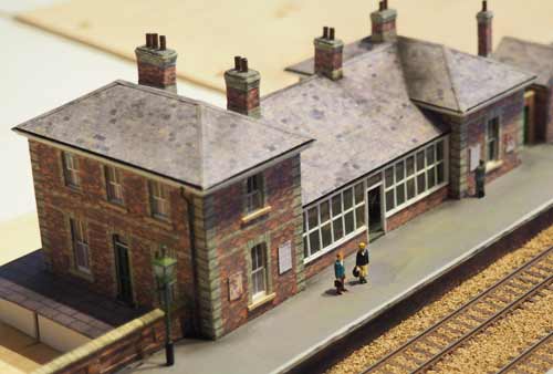
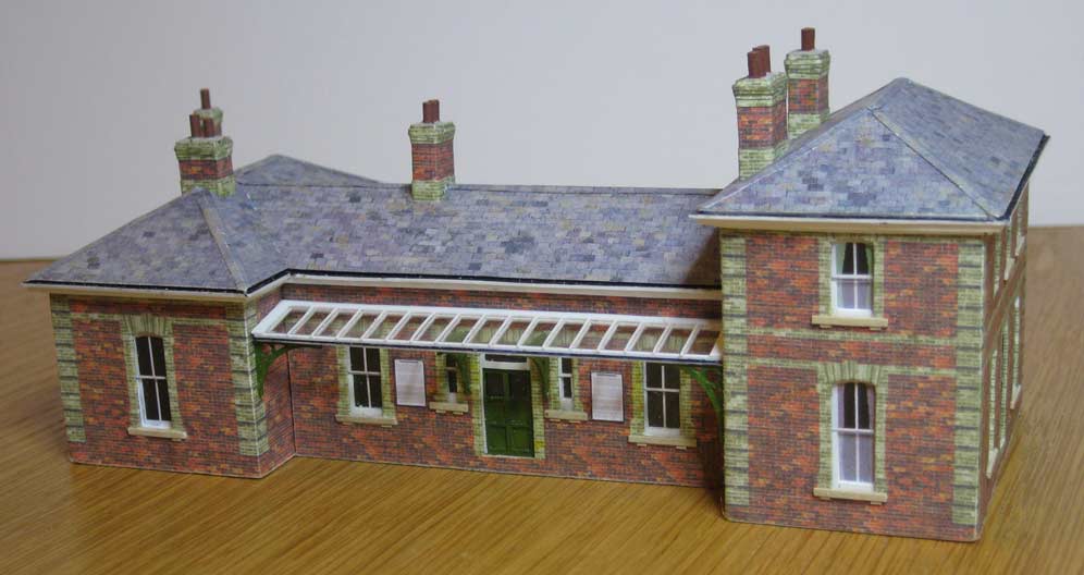
I made the three sections of the building separately, starting with the station master's house, and developed a Photoshop drawing of the four walls with all the detailing around the doors and windows.

With these outlines as a guide I constructed the brickwork on separate layers. The result was printed on 80gsm paper. (The image I printed was slightly different from this, arranged so that the ends of the printed image met in the blank wall, not at a corner at this picture suggests.)

On further layers I drew the shapes of the window panes, the long curtains and the nets, printing a couple of copies on 160gsm paper.

The next job is to cut the plastikard. I opened the line drawing in the Silhouette's software program, Studio. I then drew along all the lines where cuts were required. In this screenshot I've moved the line drawing away from the (red) cutting lines.
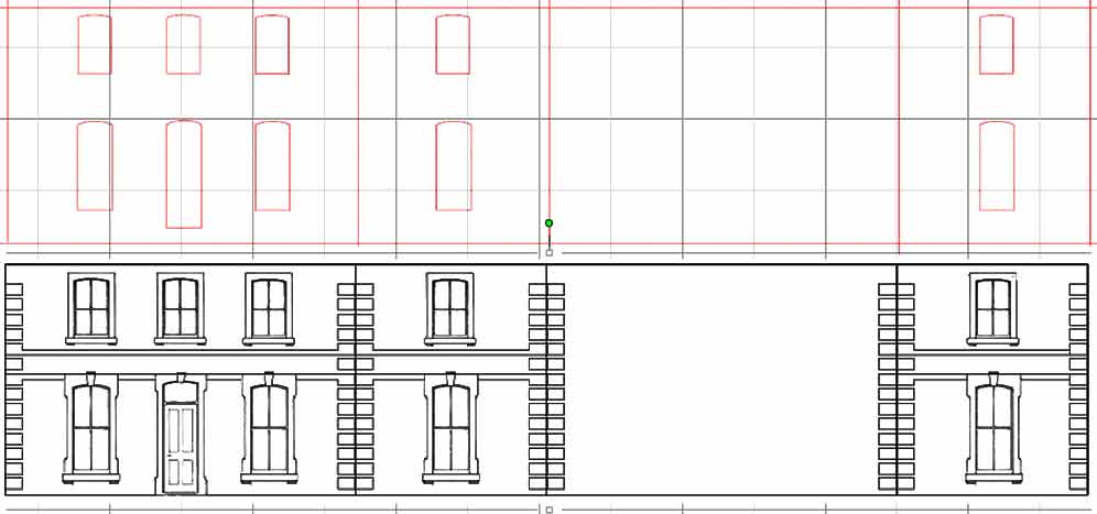
Before sending the file to the cutter I shortened the long sides by 20 thou at each end - this makes the butt joints of the 20 thou plastikard match the wrap-around brick paper. When working with that thickness plastikard the Silhouette will only score the material, it will not cut right through. So a bit of work with a sharp scalpel is required to remove the window shapes, though the walls can usually be snapped apart along the scored lines. When the walls were assembled the brick paper was wrapped around the stucture and fixed with a wash of Mek-Pak.
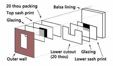
To prevent the walls bowing (which is likely to happen with such a sandwich of various materials) I lined the building with balsa wood.
When the three parts of the building were ready they were glued together and the roofs added using plastikard with printed tiles added with Mek-Pak. Chimneys, window sills and other details were added. Now came the problem of the screen enclosing a small waiting area. The Silhouette cutter was used to cut the framing from 10 thou plastikard and it was glued to the glazing material using Deluxe Materials Glue 'n' Glaze. I applied the glue, sparingly, with a cocktail stick and removed any excess from the glazing with other, clean, sticks.
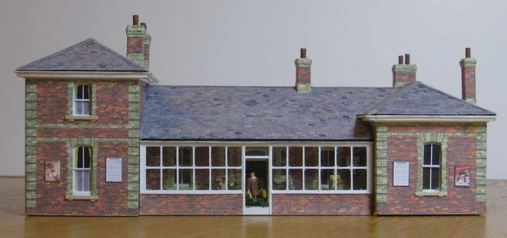
On the road side of the building the canopy was made in a similar way, except that two pieces of framing were cut. One was glued on top of the glazing material and the other below it. Small brackets were cut using the Silhouette.
November 2014
Down Platform Shelter
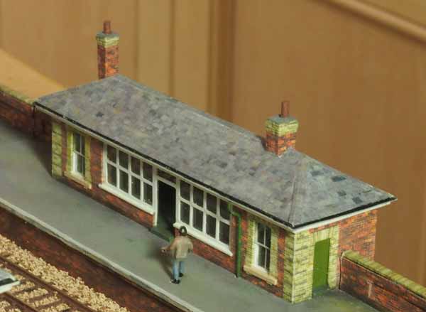
This was made in the same way as the main station building. As with the main building, the small windows are printed dummies but the large glazed area is 'see through' and was cut using the Silhouette.
December 2014
The Footbridge
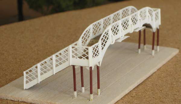
I bought a Ratio footbridge kit but didn't manage to put it together very well. So I broke it up, retaining just the actual steps and the crossing platform. The Silhouette cutter was used to make the new parts.
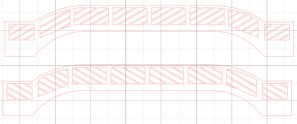
Two pieces were cut from 10 thou plastikard and glued together to form each side. Here's a screen grab of the drawings of the long side of the crossing.
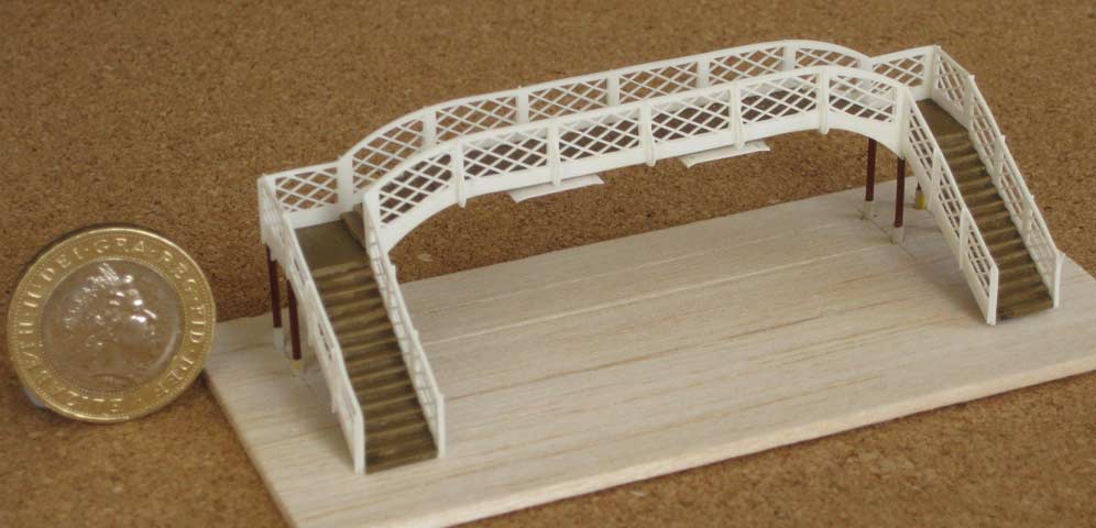
The pillars were made from plastic rod, thickened at the base with slivers of paper glued around them. Other details were added from plastic strip and Silhouette cut parts.
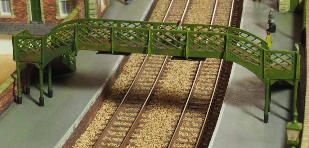
And here's the bridge in place on the layout.
Trees
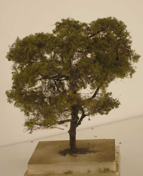
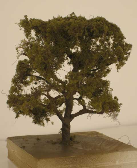
Twisting wire to make tree armatures can be done while half watching television and it made a change from the more demanding buildings. Here are some from this period.
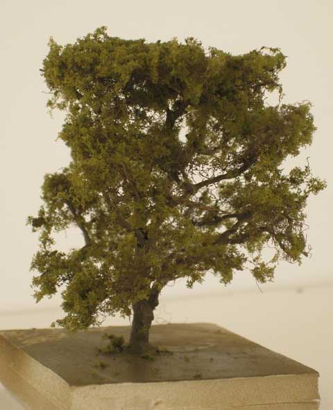
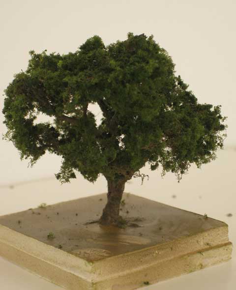
December 2014-February 2015
Platforms
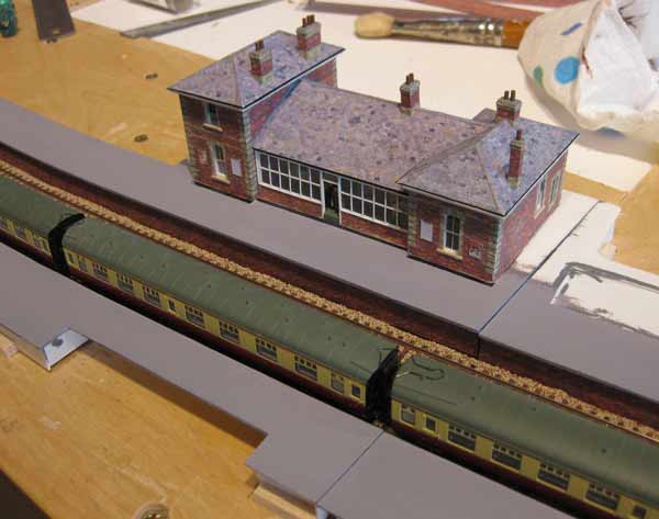
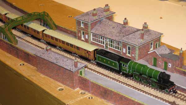
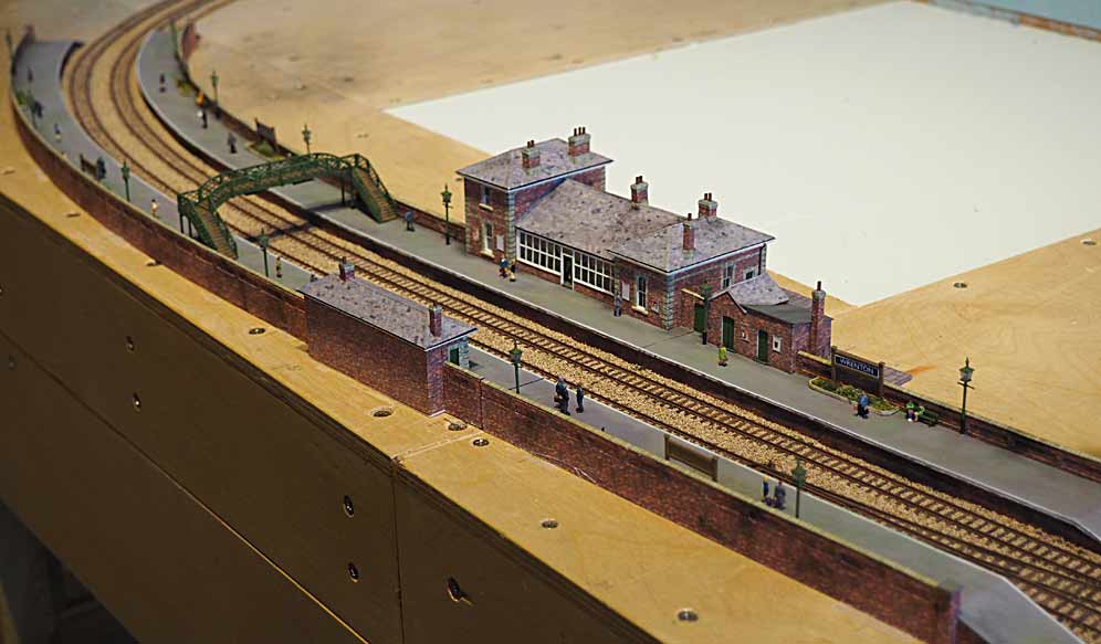
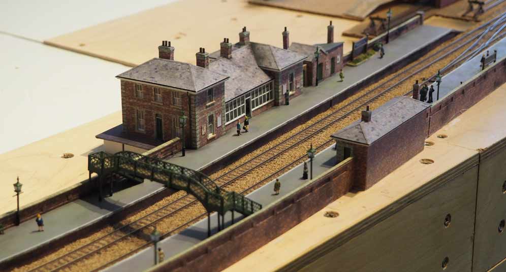
The first picture shows the main building being tried in position. A cutout in the near platform is where the smaller shelter will go. Unfortunately the platforms cross a joint in the baseboards, the levels of the platforms needed some adjustment when this photo was taken.
The figures are from several manufacturers, the seats are Peco. The lamp posts are described further down the page.
February - March 2015
The Fiddle Yard
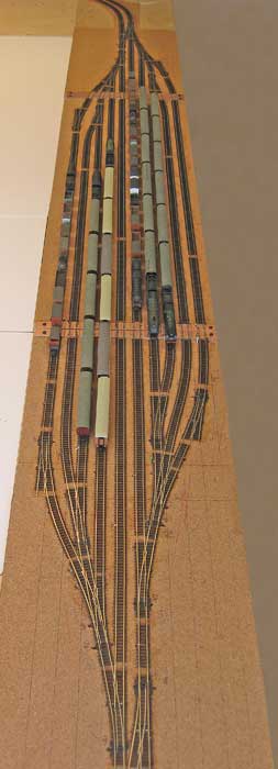
Like the scenic section's track the fiddle yard uses Peco Code 55 with electrofrog points. There are some three-way points but most of the rest are small radius ones - necessary to maximise the length of the sidings.
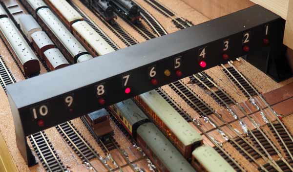
At each end of each road is a short isolated section of track and the power feeds to these sections are routed through the switches on all the point motors which have to be set to route the storage road to the main line. Thus a train can't move unless the route is correctly set. A feed is taken from each of these sections and used to light an LED indicating the selected road.
April 2015
Backscene
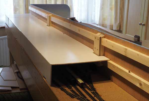
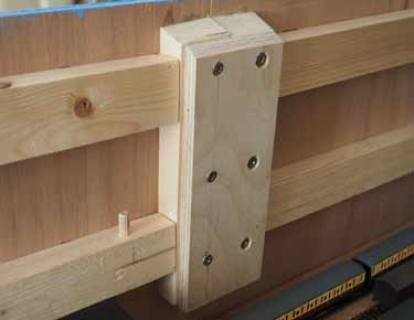
To keep the ply aligned bewteen the sections of baseboard I added short verticals of timber and screwed a piece of ply across them.
On the scenic side of the ply I glued pieces of Daler mounting board forming small rounded corners. A final layer of paper was stuck on top of the card hiding the joins and leaving gaps only between the baseboard sections. A suggestion of sky was painted with Alkyds, which dry more slowly than acrylics and thus make blending the various tones easier.
Platform Lamp Posts
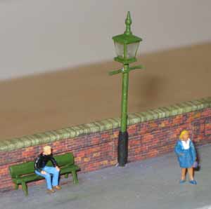
I decided to make new posts from a suitable gauge of rod. The cross bars were made from a couple of strands of wire twisted together and round the post. A quick touch of solder holds them together. I cut a small square of black plastikard and drilled a hole in the middle to fit over the post and suggest the base of the lamp. The hole in the base of the Ratio lamp was drilled a bit deeper to provide a better fixing point. This is best done before removing the lamps from the sprue. The square of card, the lamp, its cover and the finial were glued together with Glue 'n' Glaze. A sliver of paper was wrapped around the base of the post.