Building Wrenton - Page 3
June-July 2014
Decision Time
I now had a small collection of buildings which could form the beginning of a village. Should I continue to build more to make a diorama or take the plunge and build a railway layout using the buildings as part of the scenery? After much measuring of possible spaces I decided that a layout was possible and started trying to work out a track plan.
Operation of the layout (otherwise known as playing trains!) wasn't a prime interest so I didn't need a complex plan. The classic double track roundie with a hidden fiddle yard at the back seemed to be the best bet. A small goods yard on one side of the main lines and a kick-back siding on the other would add to the interest. Allowing one foot width for the fiddle yard (enough space for ten tracks in N gauge) would leave enough space for a reasonable village so the decision was made and it was out to the garden shed and the woodworking tools.
The Baseboard
A further requirement was that it should be possible to dismantle the layout in order to move it to another room should this become necessary.
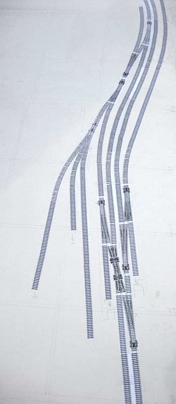
The maximum acceptable size was 2.9m by 1.07m (9'6" by 3'6") and a full size track plan was made using Peco point templates and some straight and curved track 'drawings' made using Photoshop. In order to avoid too many joints the baseboard would be divided into three sections and the drawing confirmed that making them of equal width wouldn't cause any problems when positioning the track. Given the need to keep the space below the board as clear as possible it seemed that the best solution was to construct a large four-legged supporting structure, bolted together to enable dismantling. On this the three sections of actual baseboard would sit.
Three sheets of 9mm birch ply were ordered. Two of the sheets were cut by the timber merchant into 2.44m long strips, six pieces 145mm wide (for the base) and the remainder 95mm wide (for the baseboards).
The Base
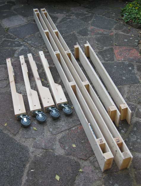
The two beams were constructed each using two of the 145mm wide lengths of ply, spaced apart by 44mm square timber. The boards had developed a slight curve and this was countered by pairing the pieces so that they were both curving outwards at the centre. The curves thus balance out and the result is straight beams.
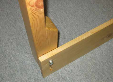
At the ends two pieces of 44mm square were fitted to be a tight fit around the legs which are made from 44mm by 66mm timber. Lengths of threaded rod (M10) pass through all three components and also fasten the end panels to the sides, the ends being two pieces of 9mm ply glued and screwed together. A further piece of 44mm square is fitted to the ends so that they butt up to the inner boards of the sides. See photo, below.
In order to provide an area large enough for the castors to be fitted an extra piece of 44mm by 66mm was glued and screwed to bottom of the legs. Small pieces of ply are fitted near the top of the legs to provide a stop when inserting the legs into the side beams.
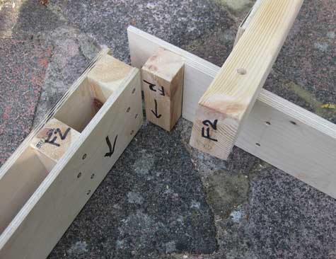
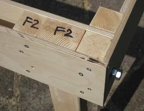
The picture above left shows one end of a beam, an end piece and a leg. And above right the leg has been inserted in the beam and the three components bolted together.
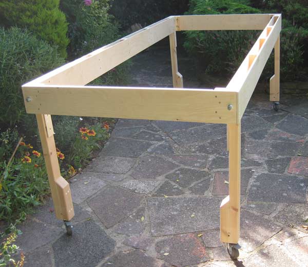
No further pieces going across the width of the structure are needed as lateral strength will be provided by the baseboards themselves.
The Boards
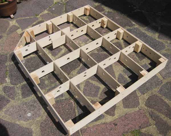
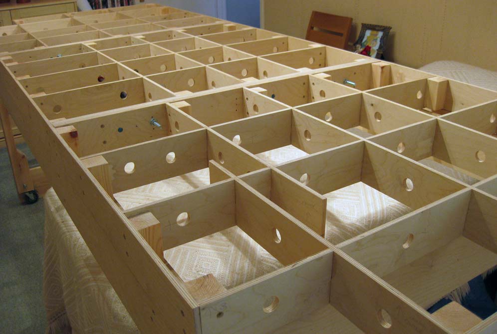
The photo, right, shows one of the three baseboard sections. The 95mm wide lengths of 9mm ply form the framework. A double thickness was used on the side that joins to the next section. Alignment is taken care of by three DCC Concepts alignment dowels.
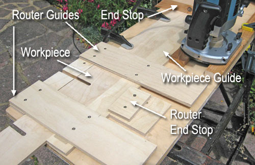
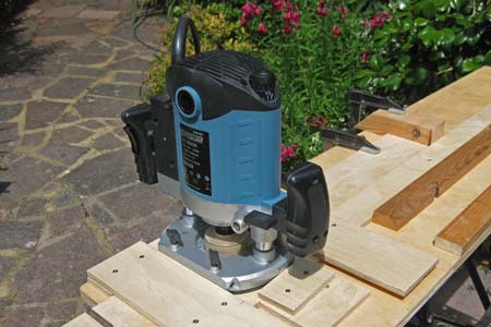
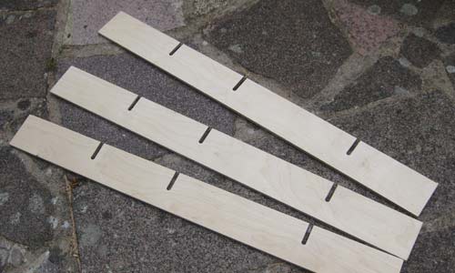
The photo should explain the constuction of the jig. The pictures below show the router in position at the end of a cut and three of the cross pieces after cutting.
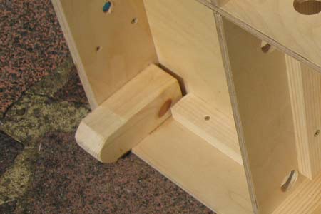
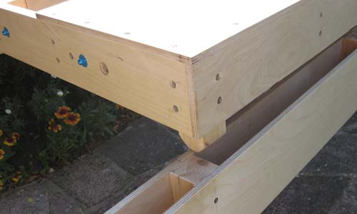
Short legs protude about 40mm and these locate in the side beams of the base structure. The central section has a leg in each corner, the side ones have just two legs. They are 44mm square timber thinned slightly to make them an easy fit into the beams. The blue objects in the right hand picture are two of the alignment dowels. These shots were taken after the top had been added.
Time for a test assembly indoors of the three baseboard sections on the base:
Back into the garden with everything, and the tops go on. Covering the whole of the framing would have needed another sheet of ply so areas which won't have any track on them were left uncovered. Here's the whole structure:
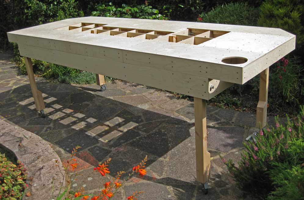
The resulting boards are very rigid and show little sign of flexing. The bare boards are manageable single-handed (they weigh about 35lbs per section) but will definitely be a two-person lift when scenery is installed to ensure that the model isn't damaged.
